 2000 and 2010 Shoemaker Grant Recipient
|
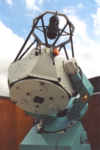
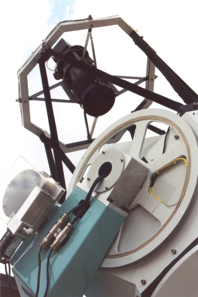
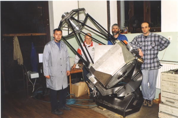
| The 60-cm Cichocki Sky Survey Telescope |
| Robotically observing since 2004 |
|
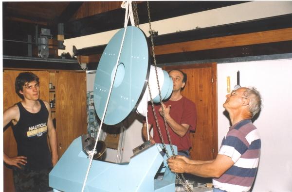
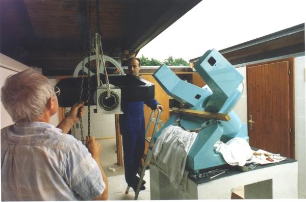
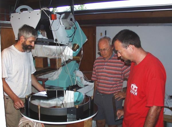
The 60-cm Cichocki telescope (named after Bruno Chichocki, an important benefactor to our
program) is an internet robotic facility, designed and built during the period
2000-2002 and put in regular operation in March 2003. It is a
world-class robotic telescope
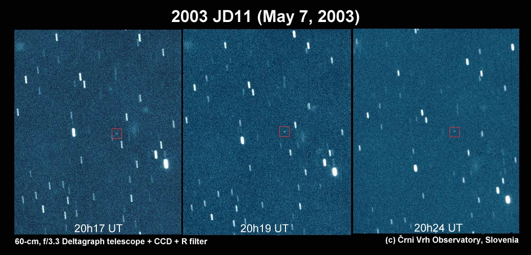
designed for wide range of astronomical observations, including search for minor planets and comets,
explosions of supernovae in distant galaxies and detection of optical
afterglows of Gamma Ray Bursts - probably the most energetic events in the universe.
It may image the sky either
in consecutive single shot or drift-scan along the great declination circles mode.
The latter technique is much more effective and preferred for scanning the sky for
asteroid and comet search under the framework of PIKA
program. Very few existing modern telescope of this class are able to use this advanced technique.
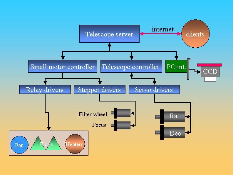
We developed dedicated hardware and software solutions that enable us real time remote control of the observatory and the telescope. Since 2004, all observations are performed in an unattended robotic mode. Custom made internet interface to a observation scheduler was introduced in 2005 for more effective and user friendly telescope targeting. Using the weather station and all-sky camera, the overnight weather situation is continuously monitored by a watchdog program. In case of sudden cloud cover, the telescope is automatically parked and the observatory roof closed. |


